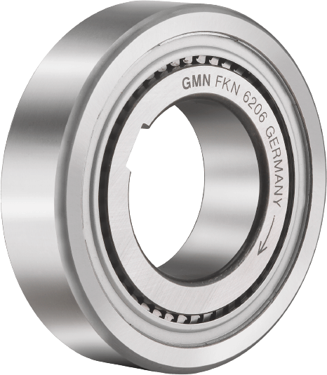


High Torque Capacity Clutches
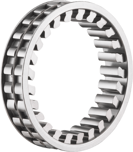
These complete units are designed with built-in roller bearings and ball bearings making it the most powerful and robust clutch in our product line. Therefore, this is great for machines that require a heavy load and high torque from the clutch.
The torque capacity of these is 53 to 588 Mn, and they have a bore (ID) size of 10 to 60 mm (0.393 to 2.362 in).
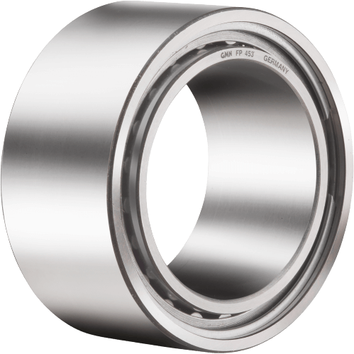
We stock GMN’s FP, FPD, FN, and FND series sprag clutch units.
Specs at a glance:
- Clutch Width (mm): 27 (open) or 34 (sealed)
- Operating Temperature: 212°F (100°C) or 284°F (140°C)
- ID Size Range (mm): 10 to 60
- OD Size Range (mm): 31 to 110
- Torque (Nm): 60 to 588
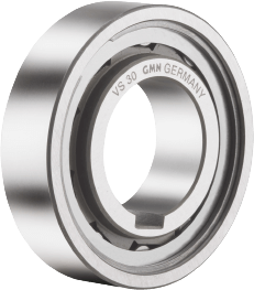
- Inner Ring: Press Fit and/or Keyway
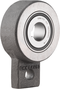
- Outer Ring: Press fit and/or Mounting Tab
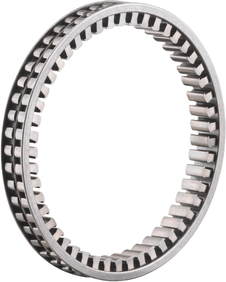
- Bearing Style: Integrated Ball and Roller Bearings
- Lubrication: Oil or Grease
- Seals: Rubber Seals or No Seals